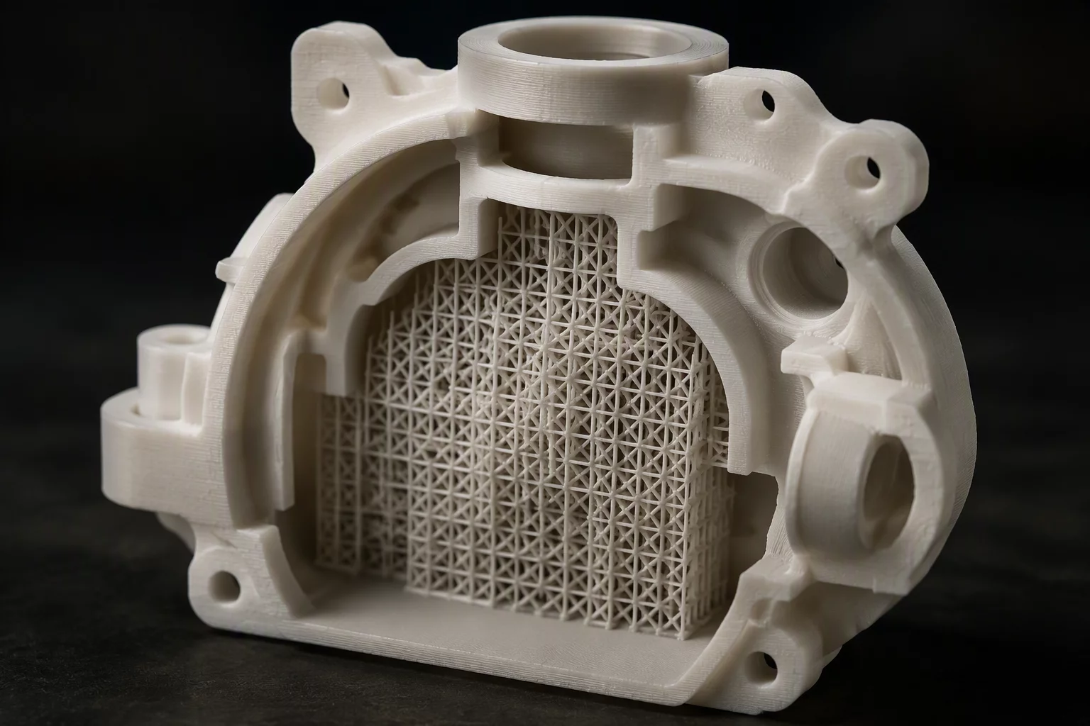
Anatomy of Internal Cavity Entrapment
Automated slicing engines often populate interior voids without accounting for physical access channels during extraction. When default configurations encounter overhangs exceeding 50 degrees inside an enclosed manifold, the generator stacks pillar upon pillar directly over lower structural floors. In this production run, standard rectilinear grids anchored themselves tightly against the ceiling of a hollow pneumatic actuator sleeve. The exterior port measured barely eight millimeters across, whereas the internal support volume expanded into a thirty-millimeter bulb. Standard long-nose pliers could neither pivot nor exert downward shear leverage against the root interfaces.
These persistent 3D print support problems arise when toolpath algorithms treat enclosed inner hollows identically to exterior eaves. Because cooling fans blow inefficiently within enclosed chambers, the extruded interface plastic remained hotter than anticipated, creating partial chemical welding between the sacrificial struts and the actual roof geometry. As a result, the intended sacrificial material turned into an unintended structural monolith inside the part. The operator faced an impossible dilemma: either crack the outer shell open to reach the debris, or abandon the airflow chamber altogether.
Mechanical Factors and Leverage Constraints
Extraction requires clear mechanical clearance vectors. Without an unimpeded entry angle, technicians cannot grip the interface skin to peel it cleanly away from the ceiling layers. In our laboratory tests, this internal failure manifested specific measurable challenges:
- Severe tool collision angles prevented dental picks from reaching the boundary perimeter where peel initiation had to occur.
- Support surface quality degraded significantly because trapped radiant heat kept interface contact layers soft, welding them to the primary ceiling.
- Debris fragmentation left loose plastic shards rattling inside the blind acoustic volume with no line-of-sight egress.
- Efforts to crush the grid using curved artery clamps snapped internal functional ribs before freeing any sacrificial pillars.
Resolving Interior Access in Future Toolpaths
Preventing trapped struts demands deliberate design alterations rather than aggressive post-processing force. Reviewing slicer settings before compilation remains the primary defense. Slicers allow users to specify support placement strictly on the build plate or paint custom manual blockers over internal recesses. When internal geometry genuinely mandates overhang reinforcement, organic branches offer narrow escape paths where rigid rectangular lattices fail. A comparative PrusaSlicer support outcome review illustrates how organic trunk systems route their structural stems outward through existing inspection ports, avoiding internal anchor traps entirely.
Bridging thresholds also deserve closer calibration. Modern filament blends easily span distances of twenty to thirty millimeters without supplementary scaffolding if chamber air movement remains uniform. Sacrificing a minor amount of ceiling flatness inside an unseen interior chamber proves far superior to entombing grams of unreachable plastic inside a functional mechanism. By raising bridge speed settings, adjusting minimum skin width, and blocking automatic generation inside blind chambers, makers produce clean cavities that need zero destructive clearing.
We lost three intake duct prototypes to this identical failure last month. Switching support placement from Everywhere to Touching Buildplate solved the problem instantly by trusting the printer to bridge the chamber ceiling.