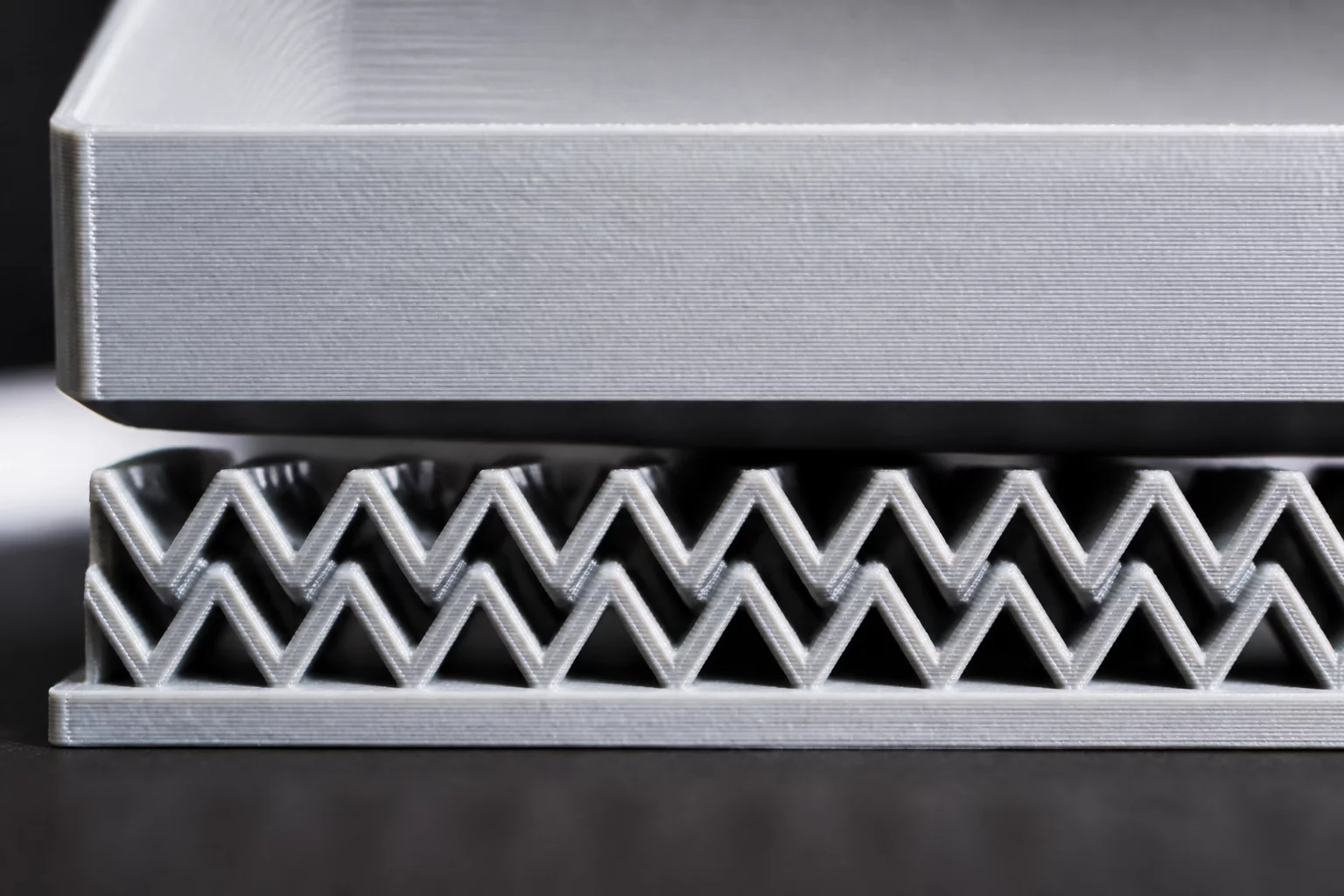
The Anatomy of a Flawless Support Interface
Support interface layers act as the mechanical boundary between sacrificial scaffold columns and functional part overhangs. Rather than allowing open infill lattices to make direct point contact with horizontal ceilings, slicers construct a dense floor or roof structure that distributes downward extrusion pressure across a continuous plane.
Achieving dimensional precision on downward-facing features requires balancing thermodynamic fusion against mechanical detachment. When molten polymer drops onto an interface deck, thermal radiation from the nozzle can weld the two structures together if the separation air gap is insufficiently sized. Conversely, excessive clearance allows the perimeter filament bead to sag under gravity, destroying fine tolerances.
Calibrating Roof Density and Contact Clearances
Standard slicer default profiles frequently specify support interface roof densities between 60% and 80%, leaving microscopic gaps that cause the supported model layer to pill or bridge unevenly. Physical inspection reveals that pushing roof density to 90-100% rectilinear or concentric patterns creates an uninterrupted bed that supports sagging strands before solidifying.
- Optimal vertical contact distance (Z-gap) sits precisely between 0.16 mm and 0.20 mm for standard 0.20 mm layer heights on PLA prints.
- Configuring 3 to 4 dense interface layers eliminates telegraphing of sparse support infill geometry onto the outer cosmetic skin.
- Adjusting interface fan speed to 100% during bridging passages forces rapid glass transition, preventing intermolecular polymer chain entanglement.
Material-Specific Strategies for Clean Breakaway
PETG and ABS exhibit significantly higher melt adhesion than standard PLA, demanding larger Z-distances or alternative interface filaments. Utilizing dissimilar materials, such as a PLA interface for PETG parts or dedicated PVA water-soluble layers in dual-extrusion hardware, permits zero-gap contact configurations that yield injection-molded surface finishes.
For single-material workflows, switching the interface pattern from rectilinear to concentric alignments along circular overhangs drastically reduces peel force. Operators should pull support interfaces parallel to extrusion raster paths rather than perpendicular to prevent delaminating structural walls during post-processing cleanup.
Reduced interface layer gap to 0.16mm on our PETG prints with organic tree supports. The contact scarring dropped significantly and overhangs at 65° remained crisp with zero sagging. Highly recommend testing the custom peel angle settings!