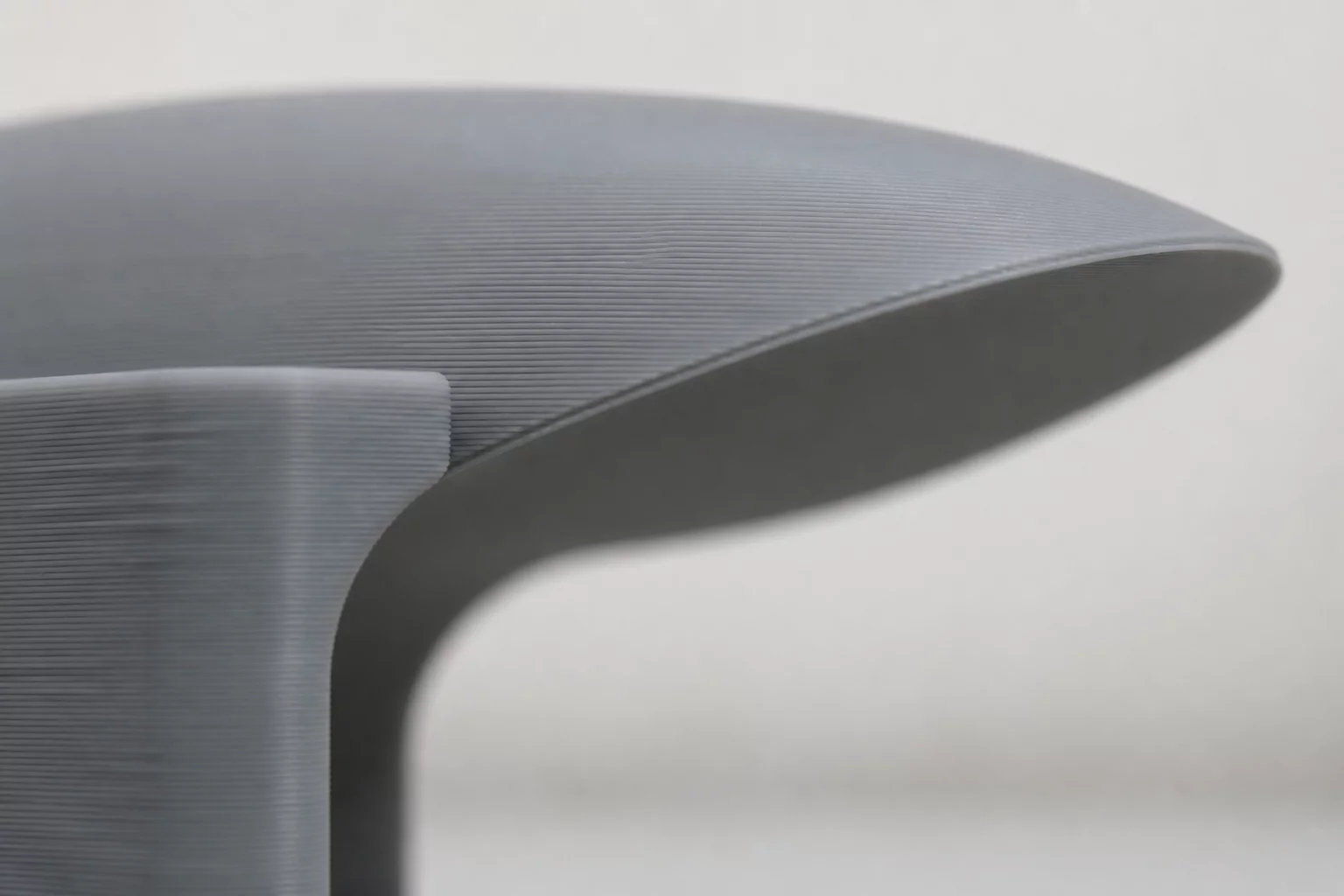
The Physics of Support Thermal Welding
Support scarring manifests when molten polymer strands from downward model skins partially fuse into sacrificial support interface roofs. When an extruded filament bead lands on an unsolidified or insufficiently spaced interface layer, the radiant heat and nozzle compaction melt both surfaces together. This thermal bond creates permanent micro-welds that rupture cosmetic perimeter contours during mechanical removal.
The key to spotless separation lies in establishing a defined micro-boundary layer where plastic solidifies before full intermolecular cross-linking occurs. Regulating temperature drops across the interface gap allows the cantilevered bridge to rest securely without chemical cohesion.
Practical Slicer Adjustments for Smooth Overhangs
Calibrating slicer settings specifically for overhang roofs eliminates pitting, string residue, and torn skin layers. Implement these core adjustments during print preparation:
- Maintain a vertical Z-contact distance equal to 1.0–1.2 times your primary layer height, preventing contact welding while offering rigid support.
- Configure 3 to 4 dense interface roof layers with an 80% concentric pattern to create an even, planar landing platform.
- Engage 100% auxiliary part cooling fan speed on bridge and supported interface layers to freeze perimeter contours instantly.
Material-Specific Handling and Post-Processing Controls
Different polymers exhibit unique thermal viscosities. For example, PETG tends to stick aggressively to support structures due to high melt adhesion, requiring an increased Z-gap of 0.22 mm and a slight extrusion multiplier reduction of 3% on interface roofs. Conversely, standard PLA benefits from an exact 0.16 mm gap and rapid print speeds across bridging vectors.
When detaching complex supports, apply lateral shear forces rather than vertical pulling tension. Twisting peeling motions along perimeter seams cleanly separates concentric interface roofs, leaving pristine surface luster with zero residual scarring.
Discussion & Peer Findings
0 RemarksNo comments yet. Be the first to share your laboratory observations on support scarring prevention.
Leave Laboratory Observation